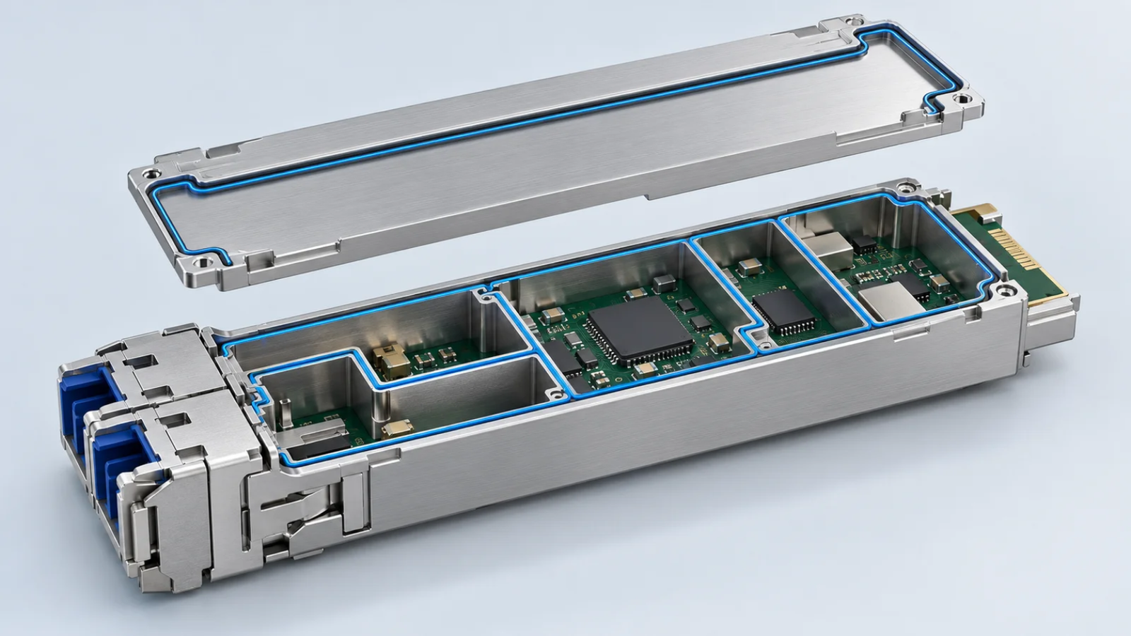
During technical exchanges with a leading optical transceiver manufacturer, our application engineering team encountered a bottleneck in a next-generation design moving from 800G toward 1.6T: achieving reliable EMI shielding within increasingly compact cavities.
The application brought mechanical loading, narrow-bead dispensing and high-frequency performance into the same design decision. Here is how we approached the case, evaluated the material options and selected a form-in-place gasket for the customer’s production process.
The challenge: small cavities and high-frequency noise
The customer’s shielding cavities were reduced to millimeter-scale dimensions, with less than one millimeter of available compression travel. Three constraints shaped the material selection.
Protecting thin zinc-alloy housings
The materials initially evaluated required substantial compression to establish stable electrical contact. In this assembly, that load risked deforming or stressing the thin zinc-alloy walls. Reducing the compression helped protect the housing but made electrical contact less consistent.
Controlling a narrow dispensing bead
The gasket had to be dispensed onto narrow cavity walls. At production volumes involving millions of units, the team needed a controlled bead profile and repeatable placement. Bead slumping and width variation were process concerns, not simply cosmetic defects.
Maintaining high-frequency shielding
Smaller cavity dimensions can shift resonant behavior toward higher frequencies. For this particular design, the material evaluation included shielding performance through 18 GHz. That evaluation range should not be confused with the optical module’s data rate or treated as the complete electromagnetic spectrum of a 1.6T design.
The evaluation: balancing contact and compression
The customer first evaluated standard conductive materials, but contact resistance fluctuated in the available compression range. More compression improved contact while increasing mechanical loading; less compression protected the housing but reduced shielding performance at higher frequencies in their evaluation.
The selection therefore needed to consider the assembled electrical contact path together with the allowable housing load and dispensing process. A material’s shielding value alone could not resolve that trade-off.
The solution: NYS-CURE® CG-5020
After reviewing the design constraints, our team recommended NYS-CURE® CG-5020, a heat-cured silicone form-in-place conductive gasket filled with silver-coated nickel (Ag/Ni). The selection focused on four aspects of this application.
Compression behavior matched to the assembly
CG-5020 has a typical compression set of ≤30% according to its English technical data sheet. Compression set and compression force describe different behavior: the set value is not proof of a low assembly force. The gasket profile, compression-deflection behavior and the actual housing load must be evaluated together. In the customer case, the selected material and assembly conditions addressed the mechanical loading concern while maintaining the required contact path.
A repeatable dispensing process
The material is intended for automated form-in-place dispensing. In this case, the engineering work included maintaining the narrow bead profile required by the cavity walls. Bead dimensions, dispensing settings and curing conditions remain application-specific process parameters and should be validated on the production equipment.
Shielding properties with their test context
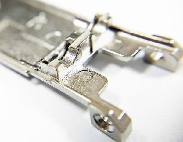
The supplied English TDS lists a volume resistivity of 0.01 Ω·cm and shielding effectiveness of ≥100 dB over 200 MHz–18 GHz, with MIL-DTL-83528C cited as the test method. These are reported material properties. They do not establish that an assembled optical module achieves the same shielding effectiveness; enclosure geometry, seams, contact interfaces and test configuration must also be considered.
Adhesion and temperature requirements
The TDS lists adhesion strength of ≥10 N/cm and an operating temperature range of −50°C to +125°C. Adhesion to the intended metal or plastic surface should be checked with its actual finish, preparation and curing process. The operating temperature range is separate from the higher temperatures used during heat curing.
CG-5020 technical reference
| Property | Typical value | Test method / condition |
|---|---|---|
| Resin / filler | Silicone / Ag/Ni | As specified in the TDS |
| Volume resistivity | 0.01 Ω·cm | MIL-DTL-83528C |
| Shielding effectiveness | ≥100 dB | 200 MHz–18 GHz; MIL-DTL-83528C |
| Compression set | ≤30% | ASTM D395 |
| Adhesion strength | ≥10 N/cm | QA-WI-054 |
| Working temperature | −50°C to +125°C | ASTM D1329 |
Source: KLEBER NYS-CURE® CG-5020 English TDS, Rev. A1.1. Values are typical and for reference; consult the complete data sheet and validate the intended application.
Download the CG-5020 English TDS (PDF) →
The result: from prototype to production
Our team supplied samples for engineering validation. In the customer case described here, CG-5020 passed the initial reliability evaluation and addressed the mechanical stress concern while meeting the customer’s EMI requirements.
The customer subsequently adopted the material in production for its 800G and 1.6T optical modules. These outcomes describe this application; they are not a general guarantee of first-pass qualification, production yield or shielding performance in another design.
Takeaway for design engineers
As available space decreases, the electrical contact path and the mechanical compression budget need to be designed together. Selecting a material that suits the gasket geometry, housing load and dispensing process can be as important as its reported shielding effectiveness.
For a new design, bring the cavity dimensions, available compression travel, housing material and finish, target frequency range, bead geometry and qualification requirements into the material review from the start.
DISCUSS YOUR APPLICATION
Working on a compact optical module?
Share your design constraints with the KLEBER application engineering team to discuss candidate materials, samples and an evaluation plan.